Determination of the Modulus of Rigidity
of a Wire using Maxwell's Needle
Measure the torsional stiffness of a wire by comparing the periods of oscillation of Maxwell's needle in two mass configurations.
Objective
Section 01Aim
To determine the modulus of rigidity η of the material of a given wire by the dynamic method using Maxwell's needle.
Learning objectives
After completing this experiment, students will be able to:
- Explain shear stress, shear strain, and modulus of rigidity.
- Describe the construction and working principle of Maxwell's needle.
- Measure the wire radius, needle length, masses, and oscillation time periods.
- Use two mass arrangements to eliminate the moment of inertia of the needle.
- Calculate G in pascals and estimate experimental uncertainty.
In the virtual lab, learners will be able to:
- Identify the solid-outside and hollow-outside configurations.
- Operate the Maxwell Needle simulation and record repeated readings.
- Verify that the difference of squared periods is used in the formula.
- Interpret the calculated modulus and compare trials.
- Recognize errors due to amplitude, timing, radius, and alignment.
Theory
Section 02Modulus of rigidity
The modulus of rigidity (or shear modulus) of a material is defined as the ratio of shearing stress to shearing strain, within the elastic limit.
For a cylindrical wire of radius r and length L, the torsional constant k of the wire is:
Here, r is the radius of the suspension wire, L is its length, η is the modulus of rigidity, and k is the torsional constant.
Principle of Maxwell's needle
Maxwell's needle consists of a cylindrical body suspended horizontally by a thin wire. When the needle is slightly twisted about the axis of the wire and released, it performs torsional oscillations.
Combining this with Eq. (1),
Experimental arrangement
The Maxwell's needle arrangement consists of a hollow cylindrical tube, two identical solid cylinders, and a suspension wire. The solid and hollow cylinders are placed symmetrically about the axis of suspension in two different configurations.
Configuration I: The solid cylinders are placed farther from the axis of suspension, while the hollow cylinders are placed closer to the axis. Let the moment of inertia and time period be I1 and T1, respectively.
Configuration II: The positions of the solid and hollow cylinders are interchanged. Let the moment of inertia and time period be I2 and T2, respectively.
This arrangement permits the difference I1 − I2 to be determined without requiring the moment of inertia of Maxwell's needle itself.
Determination of the difference in moments of inertia
Let ms be the mass of each solid cylinder, mh the mass of each hollow cylinder, and L the distance between the centres of the cylinders. The distances of the cylinders from the axis of suspension are 3L/8 and L/8.
Relation between time period and moment of inertia
Therefore,
Formula for modulus of rigidity
From Eq. (1),
Substituting Eq. (7), we obtain the working formula:
Final working formula
| Symbol | Meaning |
|---|---|
| η | Modulus of rigidity of the suspension wire |
| L | Distance between the centres of the cylinders |
| r | Radius of the suspension wire |
| ms | Mass of each solid cylinder |
| mh | Mass of each hollow cylinder |
| T1 | Time period with solid cylinders at the outer positions |
| T2 | Time period after interchanging the cylinders |
SI unit of η: N m-2 (Pa).
Note: The final expression is written in the simplified and dimensionally consistent form:
Apparatus Required
Section 03Equipment
- Inertia table with suspension wire and torsional support
- Rectangular test block or plane lamina
- Three levelling screws and spirit level
- Stopwatch or digital timer
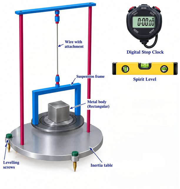
Procedure
Section 04Procedure — Verification of the Perpendicular Axis Theorem
Using an Inertia Table
- Level the apparatus: Place the inertia table on a stable horizontal surface and adjust its levelling screws until the table is properly level, using a spirit level.
- Determine the natural period of the unloaded inertia table: Place the circular inertia table on its support and ensure that it is properly balanced and free to rotate about the suspension wire. Give the table a small angular displacement and release it gently to produce torsional oscillations. Measure the time t0 required for 20 complete oscillations using a stopwatch. Repeat the measurement and determine the mean value. The period is T0 = t0/20.
- Measurement for rotation about the Z-axis: Place the rectangular block centrally on the inertia table with its base parallel to the XY-plane, so that its centre of mass lies on the axis of rotation. Give the table a small angular displacement and release it gently. Measure the time t1 for 20 complete oscillations and calculate T1 = t1/20.
- Measurement for rotation about the X-axis: Reorient the block so that its base is parallel to the YZ-plane, while keeping its centre of mass coincident with the axis of rotation. Give a small angular displacement and release the system. Measure the time t2 for 20 complete oscillations and calculate T2 = t2/20.
- Measurement for rotation about the Y-axis: Reorient the block so that its base is parallel to the ZX-plane, with its centre of mass still on the axis of rotation. Measure the time t3 for 20 complete oscillations and calculate T3 = t3/20.
- Repeat the measurements: Repeat the measurements of t0, t1, t2, and t3 at least three times and determine their mean values to reduce random errors.
- Verification: Use the measured values of T0, T1, T2, and T3 to test the relation T12 = T22 + T32 − T02. Agreement within the experimental uncertainty verifies the Perpendicular Axis Theorem of Moment of Inertia.
Important Experimental Precautions
- Use only small angular displacements so that the torsional oscillations remain approximately simple harmonic.
- Release the table gently without giving it an additional push.
- Ensure that the block is centrally positioned and its centre of mass remains on the axis of rotation.
- Count complete oscillations consistently and minimise timing errors while using the stopwatch.
- Keep the apparatus free from unnecessary disturbances during measurement.
Procedure (Virtual Experiment)
- Open the simulation: Open the Virtual Experiment and switch to full-screen mode for better visibility.
- Level the inertia table: Level the inertia table using the three levelling screws provided in the simulation. Adjust the screws until the table is properly horizontal and free from any systematic tilt.
- Determine the natural period of the unloaded inertia table: Click the Without Object button. Click Reset to initialize the simulation. Click Run to start the oscillation of the inertia table. The stopwatch starts automatically. Count a suitable number of complete oscillations. Click Stop after the required number of oscillations and record the elapsed time. Repeat the measurement if required and determine the natural period T0 of the unloaded inertia table.
- Determine the periods about the three mutually perpendicular axes: Place the test body on the inertia table with its centre of mass coinciding with the axis of rotation. Orient the body so that the required axis of the body is aligned with the axis of rotation. Select About Z-Axis in the simulation. Start the oscillation using Run and measure the time for a suitable number of complete oscillations. Stop the stopwatch and record the elapsed time. Calculate the corresponding period T1. Repeat the same procedure for the X-axis and Y-axis, obtaining periods T2 and T3, respectively.
- Reset the stopwatch: Click Reset after each measurement before taking the next reading.
- Record the observations: Enter the measured times and calculated periods in the Observation Table provided in the simulation.
- Verify the perpendicular-axis theorem: Use the recorded periods to calculate and compare the quantities T12 and T22 + T32 − T02. The perpendicular-axis theorem is verified if T12 ≈ T22 + T32 − T02 within the experimental uncertainty.
- Analyze the results: Use the Results & Analysis section to evaluate the measurements and verify the relation.
- Export the experiment: After completing the experiment, click Export PDF to generate a PDF report of the experimental results.
Note: Use a small angular displacement and the same number of oscillations for each measurement to maintain consistency and improve the reliability of the results.
Simulation
InteractiveObservation Table
Section 06Time Period for different positions
Result and Analysis
Section 07Calculation
Use the mean readings in the expression below. Since the period is squared, accurate wire-radius measurement is especially important.
Record your calculation
MCQs: Verification of the Perpendicular Axis Theorem of Moment of Inertia
Level: Moderate · Select the most appropriate answer.